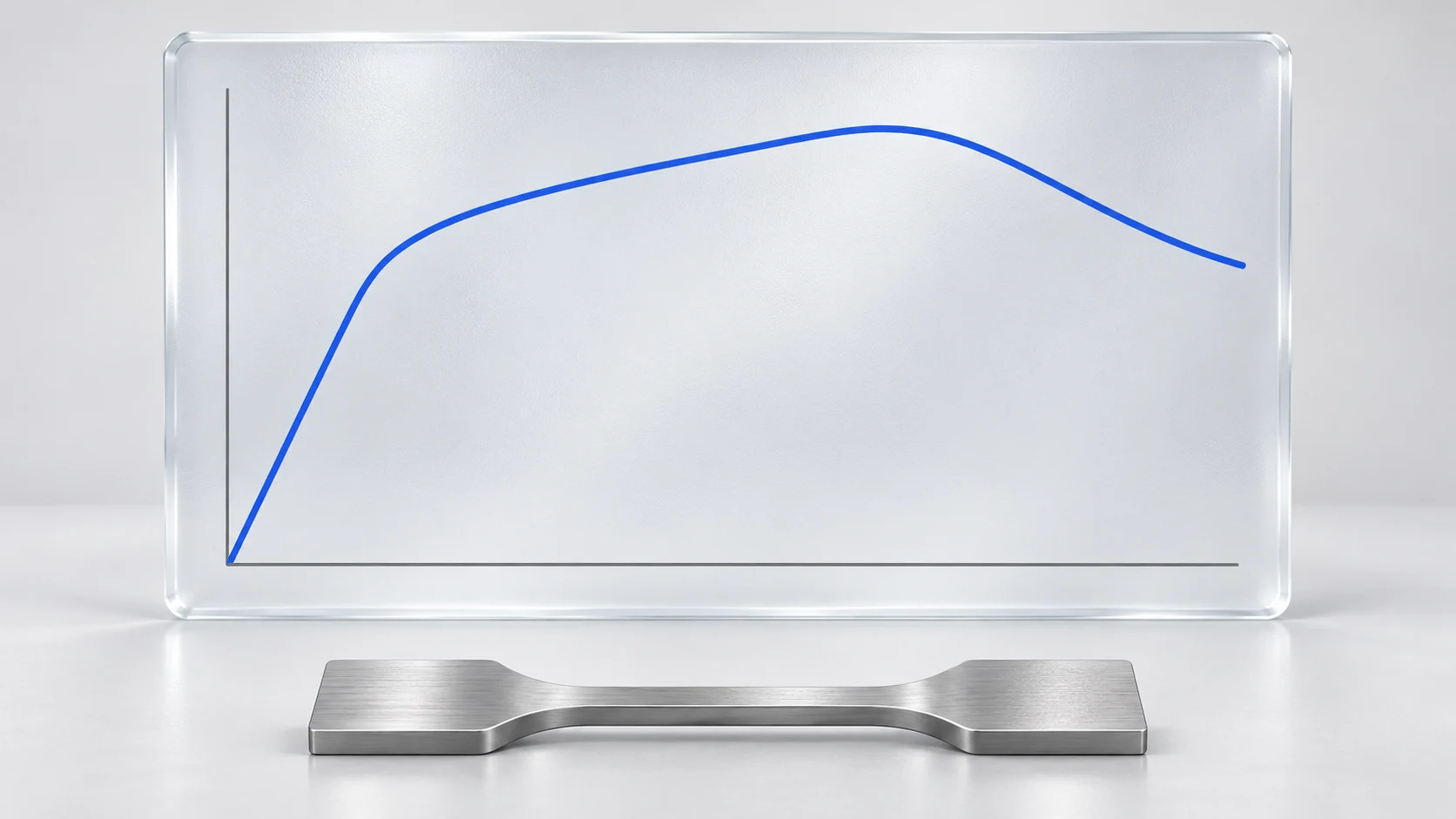
A curve that rises and then turns does not, by its shape alone, tell you how strong or ductile a material is. Start with the axes. A stress–strain curve relates stress to strain during loading; the properties it supports depend on the material and test method. [1]
Distinguish force–displacement from stress–strain
Engineering stress uses original cross-sectional area: σ = F/A₀. Engineering strain uses original gauge length: ε = ΔL/L₀. Converting load and extension therefore requires the corresponding initial dimensions. [2] Simply relabelling a graph in N and mm as MPa and % does not perform this conversion.
Record both axis labels and units, then check specimen dimensions, gauge length and the deformation channel selected in the software.
Crosshead travel includes more than gauge-section extension
Crosshead displacement can include machine and load-train deformation and grip seating. It is not inherently equal to extension within the specimen’s gauge section. An extensometer measures deformation over a defined region on the specimen, a distinction that is particularly relevant at low strains or with stiff specimens. [3]
Illustrative calculation: if a 50 mm gauge length actually extends by 1 mm, engineering strain is 1/50 = 2%. If the 1 mm value describes only crosshead travel, it does not establish 2% strain within that gauge length. These are hypothetical values, not test data.
A slope may describe stiffness rather than modulus
A force–displacement slope has units such as N/mm and describes the stiffness relationship of the measured arrangement. Modulus is evaluated from stress and strain. In the elastic region, a secant modulus uses the change in stress divided by the change in strain between two points; use the interval and procedure specified by the applicable method. [5] An arbitrary straight-line fit across an entire curve is not automatically an elastic modulus.
Compliance correction has a defined scope
System compliance depends on the configuration and applied forces. A suitable correction can improve displacement estimates, but it does not automatically satisfy every strain measurement requirement. The applicable standard determines whether an extensometer is required. [4] Keep raw crosshead travel, corrected displacement and extensometer readings clearly identified in the record.
What to retain when comparing curves
- Axis labels, units and definitions of the plotted quantities.
- Original area, gauge length, material and specimen identifier.
- Deformation source: crosshead, corrected displacement or extensometer.
- Test method, edition, loading conditions and data-processing settings.
- The result being compared and its evaluation point or interval.
Saving this information alongside the curve makes review more useful than retaining a screenshot alone. The cover illustration introduces the topic; it is not measured performance data or a universal curve shape for all materials.